

Project
Details
-
Date: Fall 2025, Spring 2026
-
Objective: Design and manufacture a LOX fill line, including a quick disconnect system, for a hybrid rocket to simplify launch and test operations, and minimize effects of cryogenic boil off.
-
Key elements: GN2 systems, LOX systems, method of retention, method of actuation
-
Role: Responsible Engineer (aka Project Lead)
-
Achievements (as of February 2026):
-
Critical Design Review passed
-
QD design finalized, verified with test piece
-
Check valve fully machined
-
Fill line parts finalized and ordered
Cryogenic Liquid Oxygen Fill System
Project Overview
In my first year at the Columbia Space Initiative, I worked to develop a passively activated nitrogen quick disconnect (QD) system for our launch vehicle, which resulted in a successful launch. This year, I have taken an increased responsibility as the responsible engineer for an even more complex and performance increasing part, a cryogenic liquid oxygen (LOX) fill system, with a quick disconnect as the main focus.
While the nitrogen disconnect was necessary to allow abort, a LOX QD was not strictly needed due to dedicated abort valves. However, the lack of a LOX QD made the team’s life difficult in several ways. For one, it made our fill procedure much more clunky. To prepare for engine fire, the team first had to fill completely with LOX while keeping members at the pad wearing specialized cryogenic gear to disconnect the line when full. These team members would then have to store the line and the LOX dewar, before quickly retreating to a safe area before GN2 fill could begin. Not only was this a clunky system which added time and effort to our launch and test operations, this also allowed heavy amounts of boil off. Because LOX exists at cryogenic temperatures, once out of the dewar, much of the LOX would begin to immediately boil off in the tank through a vent valve. Calculations found that during a 17 minute period in which the COPV was filled, about 16 pounds of LOX would boil off. Our LOX tank last year was designed to hold 35 pounds of LOX, representing a 46% loss of oxidizer under nominal conditions. That loss of performance would be magnified due to an increase in ullage volume caused by the boil off, giving the nitrogen more space to expand into and decreasing the time spent at maximum operating pressure. This amount of performance loss was deemed unacceptable by the team, thus, development of a cryogenic, liquid oxygen quick disconnect was considered necessary. Filling the tank through a QD would enable team members to retreat immediately during filling procedures, and would enable top-off of LOX to the vehicle during nitrogen fill, drastically reducing the effects of boil off, and decreasing the ullage volume in the tank.

Because of added components and complexity, a re-design of the entire LOX fill line was necessary to accommodate the QD. This included not just the design of the QD itself, but of various other components such as a custom cryogenic check valve, and the layout of an entirely new toggle system, and a separate GN2 line in order to facilitate the fully remote propellant loading of the vehicle.

This project marked a significant increase in both technical complexity and leadership responsibility compared to my previous design work, requiring the coordination of multiple team members to deliver a finished product. Entering the semester with uncertainty regarding new member interest, I initially focused on conveying information as clearly as possible. Drawing on my own experience as a new member, I knew how daunting the influx of technical terms and frequent meetings could be; to mitigate this, the other leads and I made a conscious effort to avoid rocket-specific jargon and prioritize open communication, ensuring new members never hesitated to ask questions. Once the core team for the fill line was established after the first month, I moved to delegate tasks. While collaborative work on a single part can sometimes yield a more refined result, I found that it often consumes excessive time and risks alienating members with conflicting schedules. Instead, I embraced a philosophy of individual project ownership. This approach allowed members to see their specific parts through from design to manufacture and launch, ultimately building greater expertise. As the Fall and Spring semesters progressed, design modifications and evolving requirements necessitated some shifts in project scope; however, throughout these changes, I ensured that every member working on the LOX line always had a clear understanding of their responsibilities and a defined goal to work toward.
To ensure the functionality of the LOX fill line, I developed a comprehensive plan detailing the system layout, necessary components, and the network of piping and fittings required for interconnection. As the responsible engineer for the system, I organized the entire line and drafted integration plans for both the LOX dewars and a separate GN2 line. Fundamentally, the purpose of the fill line is to transfer LOX from the dewar to the vehicle. To achieve this, a check valve was required to ensure the tank would seal when the hose was not attached, and a QD was needed to separate the line prior to launch. However, these components alone were insufficient to meet the goal of a fully remote fill system. A pneumatically operated ball valve was also essential to control flow. While pneumatic valves rated for cryogenic temperatures exist, their high cost exceeded our budget. Consequently, I designed a rig utilizing a standard ball valve actuated by a GN2 cylinder handle. We selected a spring-closed cylinder to ensure that a failure would not result in the line getting stuck open. The cylinder is actuated via a solenoid connected to a new low-pressure line in the GN2 system. The entire assembly connects via a series of specific fittings and adapters, as shown in the system diagram.


A critical component of the fill line is the one-way check valve, designed to seal the LOX within the tank once the QD system separates prior to launch. While several COTS alternatives existed, we made the strategic decision early on to pursue a custom in-house design. This choice was driven by three primary factors. First, a custom valve offered superior integration; by designing the valve in parallel with our oxygen tank, we were able to utilize the empty space within the end caps to house components. This resulted in a protruding length of under 1.3 inches, significantly more compact than COTS designs, which routinely exceeded 3 inches and would have complicated the packaging of other LOX system components. Additionally, this approach yielded a sturdy design that was remarkably easy to install and remove. Second, COTS check valves rated for cryogenic fluids were prohibitively expensive relative to our budget. Third, designing a custom valve provided a comprehensive, dedicated project for a new member to own.
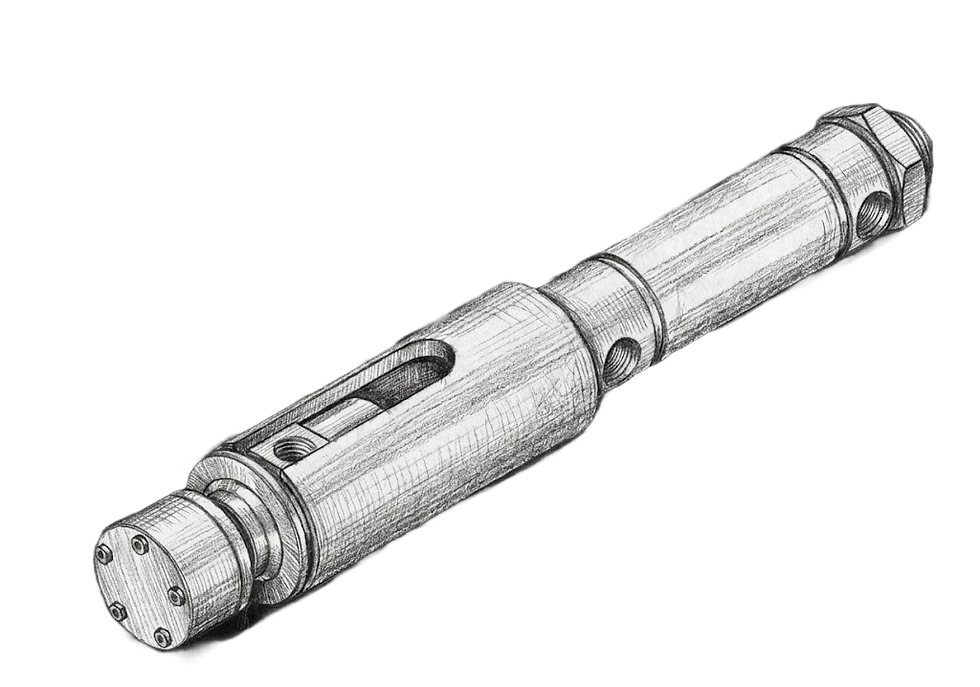
Although the check valve underwent numerous iterations to reach the final specification, the fundamental functional principles remained consistent. The assembly consists of four machined parts — an upper body, a lower body, a poppet, and a PTFE seal — along with a spring for compression and several O-rings to seal leak paths. The valve is bolted directly to the tank and uses a compression fitting to connect to the QD (creating the extruding inlet). Functionally, the poppet is normally pressed against the PTFE to form a knife-edge seal. During filling, the pressure compresses the spring further, allowing fluid to flow in one direction; once the fill is complete and the QD separates, the poppet closes to seal against the tank pressure. Throughout development, we navigated several critical design trade-offs. One major challenge was balancing spring force to create an adequate seal while maintaining an acceptable cracking pressure. We initially consulted old guidelines published by the Marquardt Corporation (now L3Harris) regarding the ratio of seal diameter to spring force for PTFE knife edges. However, adhering strictly to these guidelines, which were intended for rating seals against minute helium leaks, resulted in an extremely high cracking pressure. We ultimately decided to undersize our spring relative to those specifications, allowing us to achieve a cracking pressure under 5 psi (competitive with COTS parts) while still passing hydrostatic testing. We also optimized the body sizing for integration; as shown in the images, the spring extends beyond the upper body limits because it sits within the enclosure of the oxidizer tank's end cap, which allowed us to minimize the overall length. Finally, to ensure the valve would not become a flow rate bottleneck, we matched the valve sizing to the smallest orifice in the fill line (0.25 inches). Consequently, the poppet utilizes a 3 wing design with a flow-through surface area calculated to slightly exceed the area of a 0.25-inch diameter orifice.
The largest component of the fill line is the QD system, which facilitates the entire fill procedure leading up to launch. Early in the design phase, I established a requirement for simplicity and manufacturability, aiming to leverage system architectures we knew were reliable. However, I decided to pursue an active actuation mechanism, a distinct shift from the passive mechanism used in my GN2 QD the prior semester. While the passive approach had simplified the GN2 design, an active QD offers significant advantages for LOX operations, specifically the flexibility to verify separation and sealing prior to a launch attempt. This active approach was made feasible by the inclusion of a dedicated abort valve in the system, which allowed the QD to function strictly as a one-way fill point rather than requiring a two-way abort mode. A final major requirement was aerodynamic flushness. While the previous GN2 QD had a small, acceptable amount of protrusion, the LOX line, being twice the outer diameter, necessitated a design that remained completely flush with the airframe to optimize vehicle performance.
Throughout the design process, we iterated on several concepts driven by this push for simplicity. The first design explored consisted of a pair of double-acting GN2 pistons mounted to a housing. In this configuration, pads at the end of the cylinders provided compressive force to seal the interface and keep the system attached; before launch, the cylinders would extend, creating clearance for the ground-side QD to retract. This concept was ultimately rejected due to mass and integration risks. Counteracting the moment forces would have required two cylinders, resulting in an excessively heavy part. Furthermore, the actuation mechanism required the cylinders to extend toward the vehicle to separate, meaning a significant portion of the hardware would remain within the airframe’s inner diameter immediately following separation. This would have necessitated an excessively large cutout and posed a high risk of the cylinders snagging on the vehicle interior during ascent.
Following this rejection, we developed two further designs for a preliminary design review. One concept was an evolution of the previous year's GN2 QD, utilizing a clip mechanism to hold the halves together, but actuated by a ground-side GN2 cylinder rather than vehicle motion to maintain the active requirement. While this design utilized a proven locking method and solved the interference issues of the piston concept, it was not selected. The primary drawback was that it could not easily achieve a flush profile without requiring an excessively large cutout or a guidance ramp to ensure the clip evacuated the airframe safely. Consequently, the team and I decided to move forward with the alternative concept, which became our final design.


The final QD design is a custom, cryogenically rated adaptation of an industry standard ball locking mechanism. While similar COTS components exist, their high cost made them unfeasible for our budget. The assembly comprises five machined components: an inlet, outlet, retainer, sleeve, and cylinder housing. Sealing is achieved via a spring-assisted seal and a PTFE O-ring, while a spring and a grooveless snap ring retain the sleeve during operation. Mechanically, the system relies on ball bearings seated in divots within the retainer. In the default locked state, the sleeve is positioned over the bearings, restricting their outward motion. To connect the system, the sleeve is retracted, allowing the bearings to slide freely; inserting the inlet displaces the bearings until they drop into the retainer’s slot. Releasing the sleeve secures the bearings, locking the assembly in place. A key element of this design is the cylinder housing, which enables the entire separation sequence to occur in a single continuous stroke. Before launch, the cylinder retracts, pulling the housing forward. This motion first retracts the sleeve to unlock the bearings; once the sleeve bottoms out against the retainer, the continuing force pulls the ground side assembly away, ejecting it from the vehicle. This architecture allows for a compact diameter and ensures the QD remains completely flush with the airframe. Even further, once ejected, an aerodynamic flap on a spring-loaded hinge covers the cutout in the airframe, leaving a smooth surface. This final design was the result of a significant optimization process. The initial concept, drafted by a team member, originally required seven complex machined parts and a custom face seal. Recognizing the manufacturing risk, I proposed substituting the custom seal with a standard COTS rod seal. This change simplified the geometry, reduced the part count to five, and lowered the machining burden, making the design feasible for in-house production.
As of February 2026, significant progress has been made in the completion of the fill line. Major design work was completed before December, with critical design review being passed in January. Given its critical role in hydrostatic testing, the check valve was prioritized for manufacturing; it has since been machined and successfully proofed to the expected tank pressure of 450 psi. Fittings for the entire line have been ordered, and will be ready to support cold flow tests in March. Regarding the QD, manufacturing was assigned a lower priority as initial testing can proceed by filling through alternative ports, though fabrication is on track for completion by the end of February. In the interim, we made a nylon SLS printed prototype to verify the locking mechanism, with the video showcasing the design's mechanical soundness. So much work has gone into this project, and it already represents the most significant engineering work I have ever accomplished. I am so proud of the team who worked with me on this, and can't wait to meet the rest of our goals! This year, the team hopes to build on our accomplishment of becoming the first US based college team to launch a LOX-hybrid vehicle by reaching an altitude greater than 50,000 feet at the FAR-OUT competition in late May this year. I am confident that this QD will allow us to meet that target. More updates on the project will follow once manufacturing and further testing is complete.

